IC Anaerobic Reactor Tower
When treating medium- to high-strength organic wastewater, the goals of "high loading, small footprint" must be balanced with stable operation and energy recovery—yet conventional UASB is already approaching its loading limit. The IC (Internal Circulation) anaerobic reactor is built around a "high height-to-diameter ratio tank + two-stage reaction chambers + biogas-driven internal circulation." Using biogas production as the driving force, it forms a sludge-water circulation inside the reactor, greatly improving mass transfer efficiency and volumetric loading. It is the preferred high-efficiency anaerobic equipment for industries such as brewing, starch, papermaking, and chemicals.
I. Product Positioning
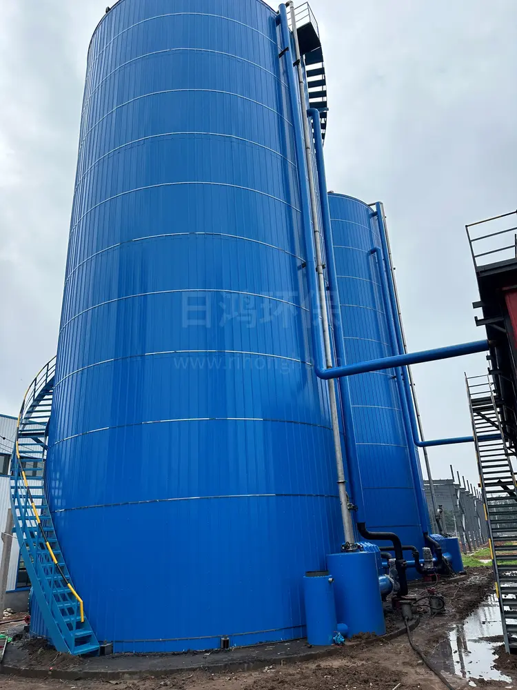
The IC anaerobic reactor is a third-generation high-efficiency upflow anaerobic reactor. The tank is tall and slender with a large height-to-diameter ratio (H/D typically 4–8). Internally, it consists of upper and lower reaction chambers and a top gas-liquid separator: the lower first reaction chamber rapidly degrades organic matter under high-concentration granular sludge and high loading while producing large amounts of biogas. The biogas carries the sludge-water mixture upward through the riser pipe, and the top gas-liquid separator discharges the biogas while returning the sludge-water mixture to the tank bottom, forming internal circulation (IC), enhancing mass transfer and diluting the influent. The upper second reaction chamber provides further polishing under lower loading. The equipment has no packing, is compact in structure, and occupies little space. It is a high-efficiency upgrade of UASB (higher loading, smaller footprint, but also higher cost and manufacturing precision requirements).
II. Working Principle (Brief)
Uniform bottom water distribution: Raw water enters the first reaction chamber from the bottom distribution system and is evenly distributed at an appropriate upflow velocity.
High-load degradation in the first reaction chamber: High-concentration granular sludge rapidly degrades organic matter in the lower high-load zone, producing large amounts of biogas.
Biogas-driven internal circulation lift: Biogas entrains the sludge-water mixture upward through the riser pipe to the top gas-liquid separator, where biogas is separated and the sludge-water mixture returns to the tank bottom, forming internal circulation, enhancing mass transfer, and buffering shocks.
Advanced treatment in the second reaction chamber: Incompletely degraded organic matter enters the upper low-load reaction chamber with the internal circulation sludge-water mixture for further stable removal.
Three-phase separation: The top three-phase separator separates biogas, treated water, and sludge—biogas is collected, sludge is retained, and clear water overflows.
Biogas utilization and effluent: Biogas is used for power generation or combustion after pressure stabilization and purification; the clarified water is discharged to subsequent aerobic/advanced treatment to meet standards.
Process flow: Raw water → bottom water distribution → high-load biogas production in the first reaction chamber → internal circulation lift (gas-liquid separation and return) → advanced treatment in the second reaction chamber → three-phase separation → biogas utilization + clear water effluent.
III. Core Advantages
① Ultra-high volumetric loading Internal circulation enhances mass transfer, and volumetric loading can reach 15–30+ kgCOD/(m³·d), far exceeding conventional UASB.
② Minimal footprint Tall, slender tank with a high height-to-diameter ratio; for the same treatment scale, the footprint is only 1/2–1/3 of UASB.
③ Strong shock resistance Internal circulation reflux dilutes the influent, providing good buffering against fluctuations in water quality and quantity.
④ Fast start-up, high efficiency High granular sludge concentration and good mass transfer enable rapid start-up and recovery, with COD removal of 80%–90% or more.
⑤ Biogas production, energy recovery Simultaneous methane production can be used for power generation or combustion, reducing carbon emissions and adding benefits.
⑥ No packing, easy maintenance Simple structure, no clogging risk, and relatively convenient operation and management.
IV. Main Technical Parameters (Typical Range Reference)
Item | Typical Range / Description |
|---|---|
Applicable COD concentration | About 2000 mg/L or above (medium- to high-strength organic wastewater) |
Volumetric loading (mesophilic) | About 15 – 30+ kgCOD/(m³·d) (much higher than UASB) |
Height-to-diameter ratio H/D | About 4 – 8 (tall, slender tank) |
Hydraulic retention time (HRT) | Several hours to 1 day (depending on concentration and design) |
Operating temperature | Mesophilic about 30–38°C (preferably 35°C±2) |
COD removal rate | About 80% – 90% or more (depending on biodegradability) |
Biogas yield | About 0.35 – 0.5 m³/kgCOD(removed) |
Methane content in biogas | About 50% – 70% |
Main body form | Steel/concrete high height-to-diameter tank, with two-stage reaction chambers and internal circulation system |
Note: The above are typical engineering range reference values. Actual operation is affected by influent concentration, biodegradability, temperature, alkalinity, and inoculated sludge, and should be determined by design calculations and start-up commissioning.
V. Typical Application Scenarios
Industry / Wastewater Type | Applicability Description |
|---|---|
Brewery / beverage wastewater | High COD, easily degradable; a classic IC application scenario |
Starch / sugar wastewater | High-strength organic; IC preferred when footprint is limited |
Papermaking / pulping wastewater | High-strength organic; inhibitor concentrations need to be controlled |
Chemical / pharmaceutical organic wastewater | For those with good biodegradability, high-load reduction |
Food fermentation wastewater | Citric acid, monosodium glutamate, amino acids, etc.; easily degradable |
Yeast / alcohol wastewater | Ultra-high concentration; IC as efficient anaerobic pretreatment |
Landfill leachate | Anaerobic pretreatment to reduce loading and improve biodegradability |
VI. Applicable Boundaries and Selection Recommendations
Suitable for: Medium- to high-strength organic wastewater with good biodegradability, and projects with high requirements for footprint, loading, and shock resistance; compared with UASB, it is more suitable for high-load compact layout scenarios.
Note: ① Higher cost than UASB, with higher requirements for tank manufacturing precision, water distribution, and internal circulation structure; ② More sensitive to suspended solids (SS), sulfate, ammonia nitrogen, and toxic inhibitors; influent requires pretreatment and water quality control; ③ Low temperature significantly reduces efficiency; insulation or heating to mesophilic operation is recommended; ④ Anaerobic effluent still contains pollutants and must be followed by aerobic/advanced treatment to meet standards; ⑤ Start-up requires inoculation with granular sludge and an acclimation process, so a commissioning period should be reserved; ⑥ Distinguished from CSTR—IC has no stirring, a tall slender height-to-diameter ratio, relies on granular sludge and internal circulation, has the highest loading and smallest footprint, and is less tolerant of solids/viscous materials than CSTR.
Selection recommendations: Determine loading and volume based on influent COD, biodegradability, and temperature; mesophilic operation is preferred; emphasize uniform water distribution, internal circulation, and two-stage reaction chamber design; plan holistically with subsequent aerobic treatment and biogas purification/utilization.
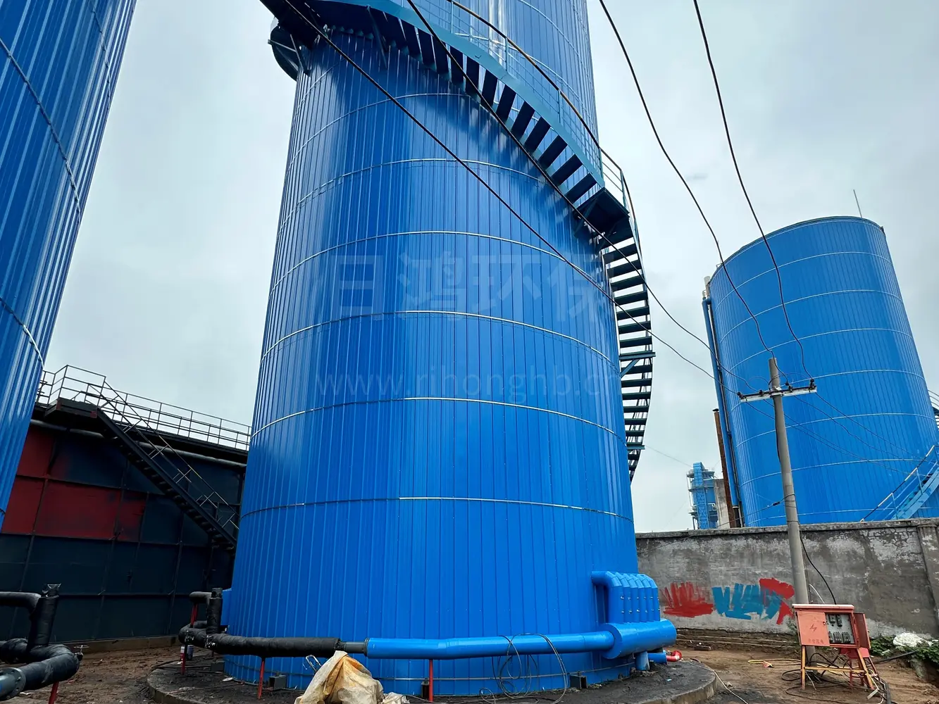
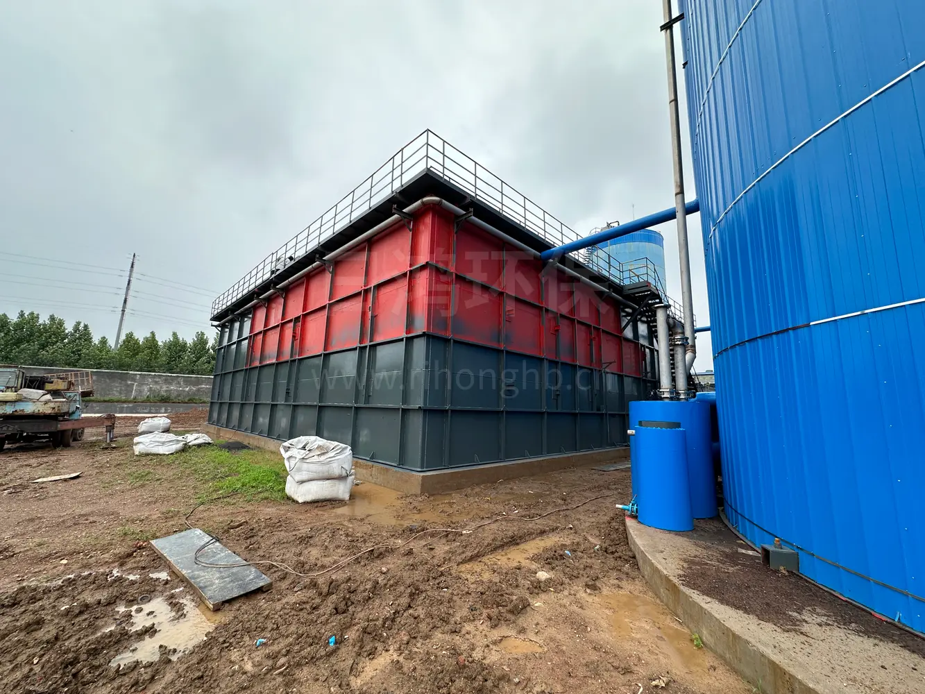
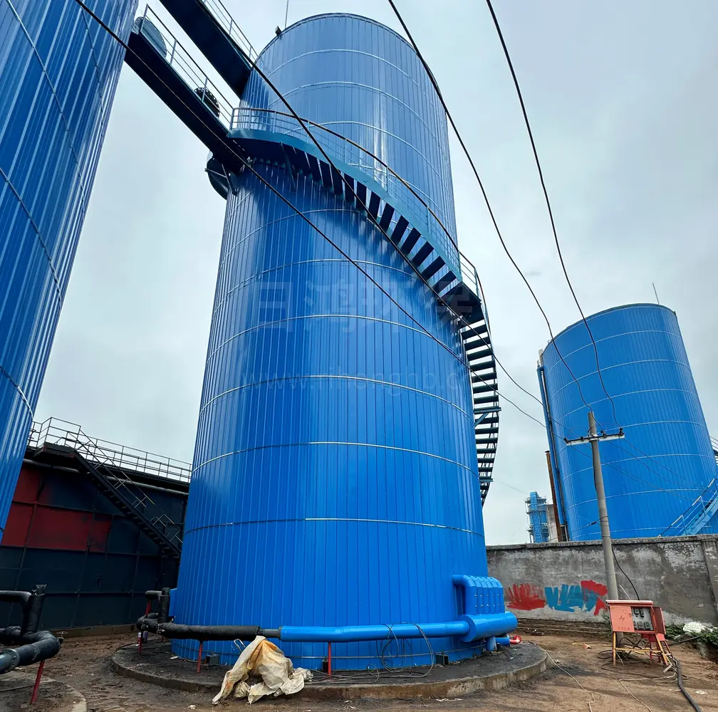
Product Images
FAQ
How much does this equipment cost?
The price varies by treatment capacity, water quality, materials and configuration, so a custom quote is provided based on your actual conditions. We offer free water testing and solution design, with a detailed quote within 1 working day after requirements are confirmed.
What treatment capacity is available? Can it be customized?
Capacity is fully customizable, ranging from tens to thousands of tons per day (e.g. 0.5–30 m³/h), with non-standard design support matched precisely to your inlet/outlet requirements.
How long does delivery take?
Standard equipment typically takes about 2–4 weeks to produce; custom projects depend on scale and process. The delivery date is confirmed at contract signing, with design, manufacturing and shipping progressing on schedule.
Is installation and commissioning included?
Yes. We provide installation, system commissioning, operator training and environmental acceptance assistance, as well as long-term managed operation services on request.
What about after-sales and warranty?
We provide a warranty period and a 24/7 technical hotline, with free repair for non-human faults during the warranty period, plus spare parts supply and regular inspection services.
High loading, small footprint, and biogas production
We can provide volumetric loading calculations, internal circulation and two-stage reaction chamber design, and start-up commissioning plans. Provide water quality and quantity, and we will give configuration recommendations for your project.
Contact Us Now →Related Products
CSTR Anaerobic Reactor
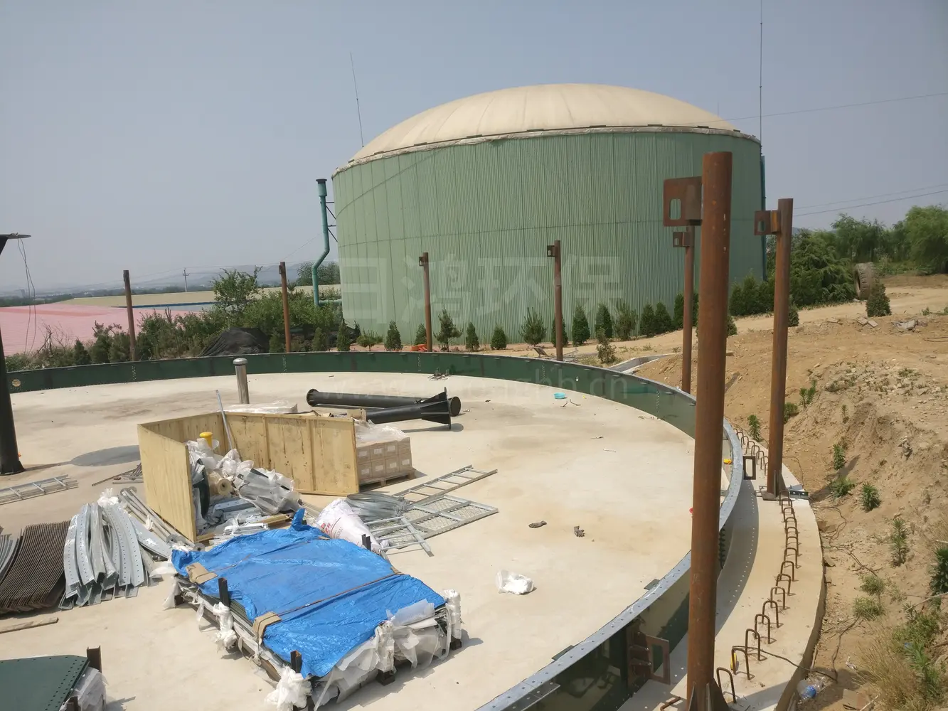
For high-concentration organic wastewater from alcohol, starch, slaughterhouse, livestock, and food processing that is difficult for biochemical pretreatment, as well as the reduction and disposal of municipal sludge and food waste, traditional aerobic processes have high energy consumption and large sludge production. CSTR (Continuous Stirred Tank Reactor) is centered on "fully mixed stirring + mesophilic/thermophilic anaerobic digestion + biogas energy recovery," converting organic matter into clean energy biogas within a sealed tank, achieving the dual benefits of "pollution reduction" and "energy production."
UASB Anaerobic Reactor
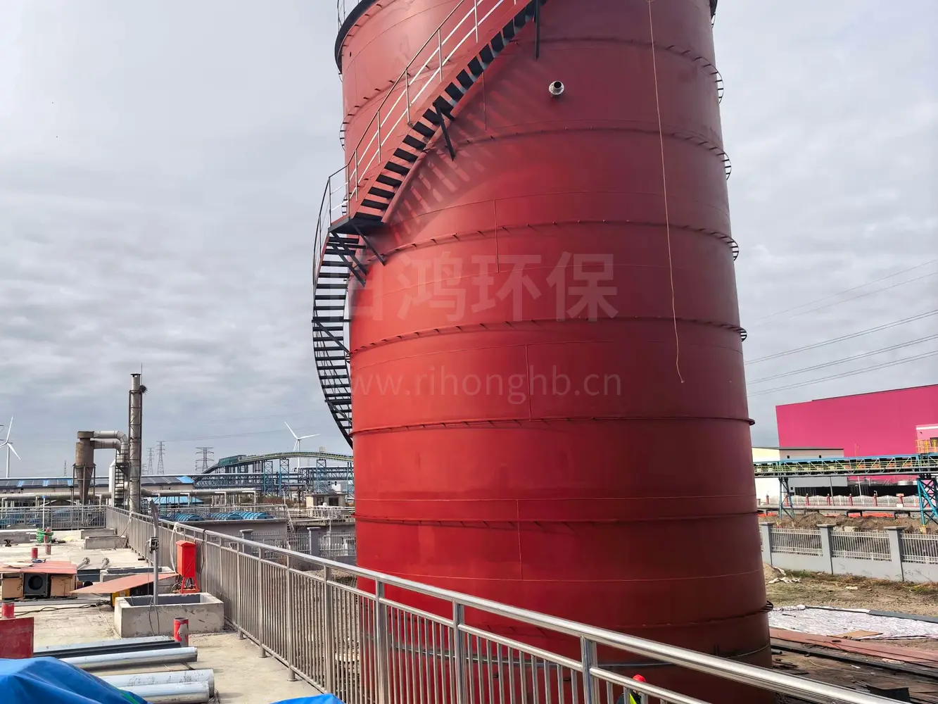
High-concentration organic wastewater from industries such as food, brewing, livestock farming, papermaking, and fermentation often faces the triple pressure of "high power consumption, excessive sludge, and expensive operation" when aerobic processes are used. UASB (Upflow Anaerobic Sludge Blanket) is built around a "high-concentration granular sludge bed + three-phase separator + no aeration required" and efficiently degrades organic matter within a sealed reactor while simultaneously recovering biogas. It is the preferred anaerobic unit for medium- to high-concentration organic wastewater with "pollution reduction, carbon reduction, and energy production."